AC Circuits Questions and Answers

Physics
AC Circuitst s Fioned What should Breaks down x 2 5 1 kV e is at x 0 atrio both a E b BAAN the initial currents through each resistor after the switch is closed c steady state currents through each resistor after the switch is closed final energy stored in the capacitor after the switch is closed A time constant of the circuit when switch is opened time constant of the circuit when switch is closed R R 190 ANSWERS 7 5 10 2 unuz Co 6 A condenser of capacitance 2 uF has been charged to 200 V It is now discharged through a resistance the heat produced in the wire is

Physics
AC CircuitsAn ac signal sinusoidal output from a device is shown in the figure The average value and rms value respectively in the given case are 26 26 INCERT Pg 235 2 2 2 b b

Physics
AC CircuitsAn ac supply is connected across a series LCR circuit If capacitor is removed then which of the following phasor diagram may be correct NCERT Pg 245 fee 1 3 KIZ 13 2 4 1 6

Physics
AC Circuits6 In the circuit shown in the figure The voltmeter and ammeter reading will respectively be source voltmeter and ammeter are ideal NCERT Pg 245 25 2 50 12 www R 220 V 1 0 V 2 2 A 3 110 V 2 2 A 250 0000 L C our 2 0V 4 4 A 4 110 V 3 A

Physics
AC Circuits11 A resistor of 100 2 is connected in ser with series combination of inductor capacitor If XL and Xc are the reactance inductor and capacitor respectively reactance of circuit will be NCERT Pg 1 IX Xcl 2 IXL Xcl 3 x x 4 X Xc XL

Physics
AC Circuits4 Capacitance C A capacitor C initially charged upto qm is connected to an inductor L The differential equation of LC oscillator is NCERT Pg 255 d q 1 9 0 dt 3 da g dt LC 0 2 di 9 0 4 d ag d1 0

Physics
AC Circuits28 A When a coil is connected current through it is zero R When a coil is connected to a battery induced emf initially is zero 1 A is true and R is true and R is correct explanation of A 2 A and R are true but R is not the correct explanation of A 3 A is true R is false 4 A is false R is true

Physics
AC Circuitsindin 10 A F capacitor is connected to a 200 1 50 Hz ac source The capacitive reactan of the circuit is INCERT Pg 24 1 1000 2 2 500 3 212 2 4 100 0

Physics
AC Circuitsviii A resistance of 1002 is joined in series with an inductance of 0 5H What capacitance should be put in series with the combination to obtain the maximum current What will be this maximum current What will be the potential difference across the resistance inductance and capacitance The current is being supplied by 200V 50Hz AC mains 20 24 F 20A 200V 3142V 3142V

Physics
AC Circuitsissage As shown in figure given tan 4 3 530 Box 1 R 30 x 40 00000 Xc 100 V fHz V 200 2 sin at f 4 Instantaneous current in branch having capacitor C will be a 20 2 sin cot 3 4 b 40 2 sin wt 4 c 60 2 sin wt 4 d None of above urrent through inductor and capacitor will be c 530 d None

Physics
AC CircuitsThe figure shows a LCR network connected to 300 V a c supply The circuit elements are such that R XL X 102 V V and V3 an three a c voltmeters connected as shown in the figure Which of the following represents the correct set of readings of the voltmeters V 100 V V 100 V V3 100 V V 150 V V 0 V V 150 V V 300 V V 100 V V 100 V V 300 V R 300 V

Physics
AC CircuitsAn input signal of frequency 50 Hz is applied to a rectifier circuit The output frequency will be 50 Hz if rectifier is full wave rectifier 50 Hz if rectifier is half wave rectifier 100 Hz if rectifier is half wave rectifier 150 Hz if rectifier is full wave rectifier

Physics
AC CircuitsAssuming that diode is ideal the output waveform for the circuit shown in the figure is R www 20sinot 20 V t 20 V Fov 5 V t Voutput

Physics
AC CircuitsIn Figure V is the potential barrier across a p n junction when no battery is connected across the junction 1 1 and 3 both correspond to forward bias of junction 2 3 corresponds to forward blas of junction and 1 corresponds to reverse bias of junction 3 1 corresponds to forward bias and 3 corresponds to reverse blas of junction 4 3 and 1 both correspond to reverse bias of junction

Physics
AC CircuitsA circuit shown in the figure contains a box having either a capacitor or an inductor The power factor of the circuit is 0 8 while current lags behind the voltage Then find the inductance capacitance of the box in S I unit Take 3 2 The circuit draws 1 ampere current Vc Vrms voltage across capacitor C Box lamp Vc 1000V

Physics
AC Circuitsiv In a given AC circuit through a specific branch the current varies as a function of time given as i isin wt 0 wt and i isinot t 2 wt Calculate the average current per cycle of this AC 1

Physics
AC Circuitsdas shown in without any 4k T EMF 5 42 The figure 5 298 shows a specific RL circuit the time constant for this circuit is A C L 2R 2R L R www oooooo E Figure 5 298 B D ER 2L R R 2L

Physics
AC Circuitsa long stant 5 51 Initially in the circuit shown in figure 3 305 the switch is in position 1 for a long time and then shifted to position 2 at t 0 as shown in figure 5 305 Just after closing the switch the magnitude of current through the capacitor is A Zero C E R ET www R ellele 2 Figure 5 305 B E 2R www R C D None of these

Physics
AC CircuitsIn the circuit shown the average power developed in the resistor R is 31 25 W 62 50 W 125 W 250 W C 500 uF 6000002 L 0 1 H R 2002 ww www R 100 50 sin 100 t

Physics
AC Circuits5 If is instantaneous velocity of particle and is velocity of wave then 1 a is perpendicular to 2 is parallel to 3 1 is equal to 1 4 101 slope of wave form
Physics
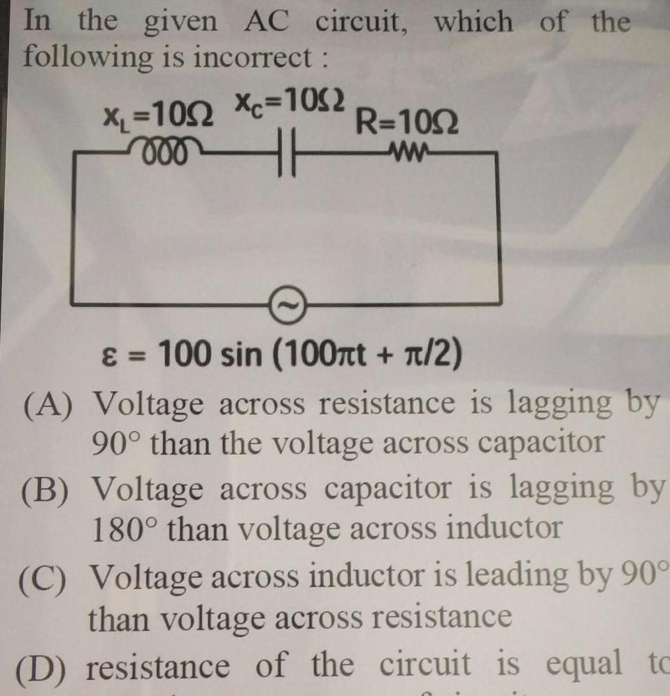
AC CircuitsIn the given AC circuit which of the following is incorrect XL 1052 Xc 1032 mot R 1092 wwwww 100 sin 100 t 2 A Voltage across resistance is lagging by 90 than the voltage across capacitor B Voltage across capacitor is lagging by 180 than voltage across inductor C Voltage across inductor is leading by 90 than voltage across resistance D resistance of the circuit is equal to

Physics
AC CircuitsConsider a series LCR circuit XL 300 R 20 0 Xc 100 The equation for ac voltage source is given as V t 100 2 sin wt Choose the correct statement s C L 6ooooo7 The equation for voltage across inductor as V t 150 sin The equation for voltage across inductor as V t 50 sin 5 wt wt 75 R www

Physics
AC CircuitsConsider a series LCR circuit C L 6000000 R XL 3002 R 20 Xc 100 The equation for ac voltage source is given as V t 100 2 sin cot Choose the correct statement s A The equation for voltage across inductor as V t 150 sin ot B The equation for voltage across inductor as V t 50 sin cot C The impedance of LCR circuit is 20 2 ohm 3 50 73 3r

Physics
AC Circuits2 C e se Ans 30 2 50 2 2 2 A 300 rad s 23 A 0 21 H inductor and a 12 2 resistor are connected in series to a 220 V 50 Hz AC source Calculate the current in the circuit and the phase angle between the current and the source voltage Ans 3 28 A tan 5 5

Physics
AC CircuitsAn ac source is initially connected to a resistor R Situation 1 If an inductor is connected in series with the resistor the impedance in the circuit is 3R Situation 2 If a capacitor is connected in series with resistor the in is 2R e cire 4 36 Situation 3 Both the inductor and the capacitor are connected in series to the resistor A In situation 3 if the phase of current and potential difference across the source is then cot pr where p is nearly

Physics
AC Circuits5 F S 30 5 F HH 30 122 80 125 12 82 B 5 F be x t between the plates 39 Three 1 2 three 82 and three 3 2 resistances and three 5 F capacitors are connected in the edges of a cube constructed by conducting wires If an ideal battery of electromotive force 12 V is connected between the two diagonally opposite corners A and B of the cube find charges on the capacitors

Physics
AC CircuitsConsider a circuit which contains only pure inductor or a pure capacitor connected to an ac source and resistor is absent Choose the correct statement 1 Power dissipated in the circuit is maximum 2 Current leads to no power dissipation and is called wattless current 3 Power is dissipated due to wattless current 4 The phase difference between source emf and

Physics
AC CircuitsA uniformly wound solenoid having an inductance L and resistance R is cut into two identical halves and the two halves are connected parallel The combination is now connected to a battery of negligible internal resistance and with emf E 1 The time constant of resulting circuit is R The rate at which the power supplied by the battery increases is 4E L The rate at which energy is stored by inductor initially is 4E R initially The rate at which energy is drawn from battery after a long time is 4E2 R

Physics
AC Circuits7 Henry in an alternating current circuit are connected to 220 volt A C mains in series The power dissipated in the circuit will be 1 1210 watt 3 440 watt 1 A resistance of 20 ohm and an inductance of 2 4 605 watt 1100 watt u vrladt faga uri aftver fo 20 de an 1 Bad an taca do 3 220 are cofft And Gigi raI3 faga oferer if fbceft UIC 22RT BT T T 1 1210 2 605 3 440 4 1100 a

Physics
AC Circuits1 0 V 2 5 V 3 10 V 4 V When an alternating voltage of 220 V is applied across a device P a current of 0 25 A flows through the circuit and it leads the applied voltage by an angle n 2 radian When the same voltage source is connected across another device Q the same current is observed in the circuit but in phase with the applied voltage What is the current when the same source is connected across a series combination of P and Q A lagging in phase by r 4 with voltage 1 2 A leading in phase by 4 with voltage A leading in phase by n 4 with voltage 2 4 2 A leading in phase by r 2 with voltage 40 1 0 V 2 3 2 1 A 4 4 2 A A 2 5 V 3 10 V 4 2 220 V A C al rifu 0 25 A fed A 4 2 ellgarfed A A 2 fa ART tipa 09990MD610919001

Physics
AC CircuitsIn the circuit shown in the figure K is open The charge on capacitor C in steady state is 9 Now key is closed and at steady state charge on C is q2 The ratio of charges 9 92 is K R 202 A 3 C 5 3 3 5 1 C R 392 Correct Answer

Physics
AC CircuitsAn Ac circuit contains two identical resistances and two identical capacitors connected as shown in the figure 1000 R 9 and C 10 F If not where is the phase angle between the source voltage and 3 potential difference between point A and point B Find the value of n R R V 200 sin 1000 You are viewing Physics su Integer Type question 13 Answered Marked for Review 15 Answered and Marked for Re will be considered for

Physics
AC CircuitsFor the shown AC ircuit List 1 contains Va VAI and phase difference between AC voltage source and Vc in degree Corresponding values In S I unit are given in List II Match the correct one A Xc 322 41 List 1 List II I Vc P 20 III I II VR 2 53 IV O Vc AC voltage source R 80 5 60 R 492 www 100 2 sin100nt Volt T 20 2 V U 127 B

Physics
AC CircuitsFor the shown AC circuit List l contains Vc VR I and phase difference between AC voltage source and Vc in degree Corresponding values In S I unit are given in List II Match the correct one Xc 392 HH 1 Vc P 20 List l List II II VR Q 53 OI Vc AC voltage source R 80 S 60 T 20 2 U 127 OI S II For the above circuit as shown match the correct one O 1 S II R III Q IV P R II 100 2 sin100nt Volt R 49 www D II R III P IV Q S III P IV Q O 1 P Il S III Q IV R 3 If additionally an inductor of inductance L 50 connected in between capacitor and resistor in series then again match the correct one O 1 Q II P III R IV S O 1 Q II R III S IV P D III B T IV D H is

Physics
AC CircuitsR y CO IL120 R 1 vooroo www 2 ashss A St sblatio trw bo soymloy bus Totais 3 do In the above circuit C F R 2002 L 2 10 R 102 Current in L R path is I and in C R path is 12 The voltage of AC source is given by V 200 2sin 100t volts The phase difference between I and I is Main 2019 12 Jan II 90 a 30 b 60 c 0 famplitude v an H and

Physics
AC CircuitsWhich of the following is are correct for alternating current circuit C R www mooooooo L In LCR series circuit current through Rat resonance is maximum In the series LCR circuit current is zero at resonance Alternating current measuring instruments is based on heating effect In an AC circuit the applied rms voltage is not equal to algebraic sum of rms voltage lomonto

Physics
AC CircuitsIn an A C circuit the instantaneous values of e m f and current are given by E 100 sin 200t volt and I 2 sin 200t Ampere The average power 3 consumed is the circuit is YOU A 200 W B 100 W C 50 W C OF W

Physics
AC CircuitsIn a circuit current changes with time according to 2 t rms value of current between t 2 s to t 4s will be O 3 A 3 3 A 2 3 A hr min O 2 2 A
Physics
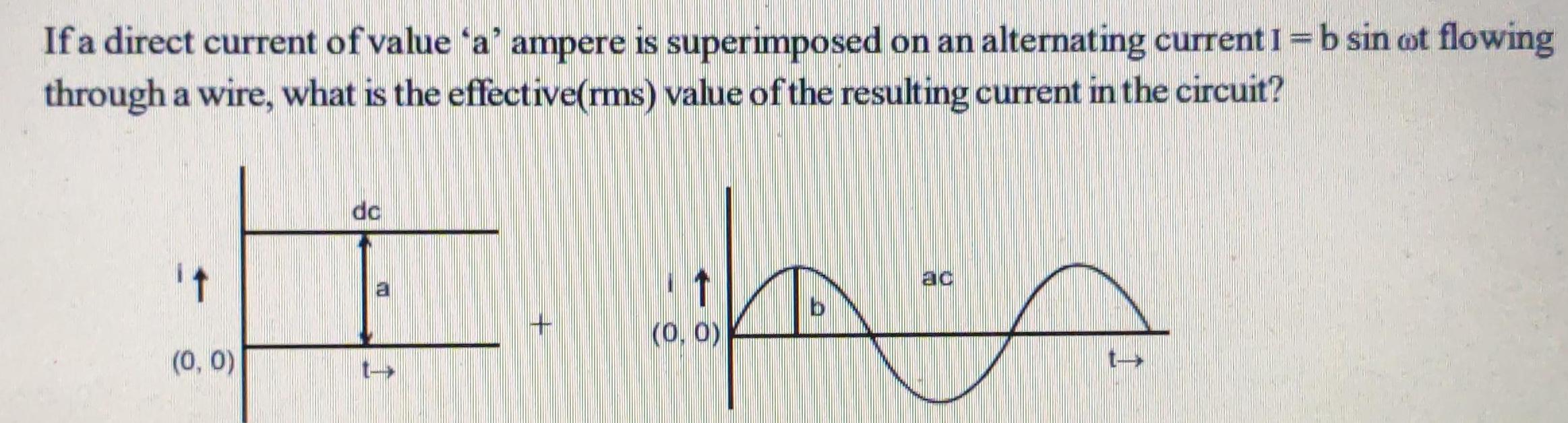
AC CircuitsIf a direct current of value a ampere is superimposed on an alternating current I b sin ot flowing through a wire what is the effective rms value of the resulting current in the circuit it 0 0 dc AS 0 0 t

Physics
AC CircuitsChoose the correct answer Consider a series LR circuit with a switch shown in figure If the switch S is closed down t 0 then the magnitude of change in through the ideal inductor in one time constant the circuit is 1 10 1 e e 1 1 000000 1H Sp 10 v www 10 2 Med

Physics
AC CircuitsFigure shows an ac circuit The rms voltage of the source is Vrms The rms current through the source when Note Do not consider radiation and other such behaviour at high frequency R R The frequency of ac generator is very low near zero is near zero is rms 2R The frequency of ac generator is very low 2V rms R The frequency of the source is very high much higher than resonant frequency is 2Vrms R The frequency of the source is very high much higher than resonant frequency is Vrma

Physics
AC CircuitsThe capacitor in the figure below is designed to filter low frequency signals impeding their transmission between circuits Circuit Signal Circuit 2 a What capacitance is needed to produce a 131 kf2 reactance at a frequency of 193 Hz nF b What would its reactance be at 1 00 MHz 2

Physics
AC Circuits40 The power factor of the circuit shown in the figure 1 is The reactance of capacitance of the 2 circuit is 4sin 2001 1 30 2 3 40 2 www 00000 0 2 H D 2 500 4 Either 1 or 2 41 Which among the following has smallest

Physics
AC CircuitsFigure shows two circuits in each case V denotes peak value of input voltage Input voltage is given by V V sinot and output voltage by V V sin at 8 0 M Vinput R www Circuit 1 V output A In circuit 1 maximum output voltage is V B In circuit 2 maximum output voltage is VM O V input 1 Vo RC R www P C In circuit 1 average power dissipated is given by Circuit 2 Vo RC D C 2R V output V 1 ORC

Physics
AC CircuitsUsing the A Y or Y A conversion determine the total impedance for the networks in figure E 60 V 0 a b C d 12 96 Q 267 13 2 71 Q Z 23 87 1515 ZT YT 2 809 420 556 8 544 Q2 20 56 20 www 92 12 22 000 www 12 Q 30 12 Q 90 92 ell

Physics
AC Circuitsnsider a series LR circuit with a switch as shown in figure If the switch S is closed down at t 0 then the magnitude of change in flux ough the ideal inductor in one time constant of the circuit is 000000 1 H B S 10 v A 10 1 6 e 1 www 1092 T

Physics
AC Circuitssider a series LR circul a switch as shown in figure If the switch 3 is closed down at 1 0 then the magnitude of change in nux ugh the ideal inductor in one time constant of the circuit is 000000 www 1 H 10 92 10 V A 10 B S CI e C e e

Physics
AC Circuits60 500 W In the power triangle shown the reactive power is a 1000 VAR lagging O b 1000 VAR leading O c 866 VAR leading O d 866 VAR lagging

Physics
AC Circuits5 The virtual current of 10 A and 100 Hz flows in an AC circuit containing a coil The power consumed in the coil is 1000 watt If the virtual voltage across the coil is 200 V then its resistance will be 1 5T 3 10 2 1 2 10m 2 4 592 D

Physics
AC CircuitsA series RLC circuit has the following values 10 e 50 V rms at R 20 XL 400 rad s Current 2 A leads the applied voltage The value of the capacitive reactance Xc is A 59 C 1022 L B D 25 Q 15 Q