Capacitors Questions and Answers

Physics
CapacitorsIf the capacitor in the circuit shown below was initially uncharged and the switch was closed at t 0 s what is the current in the circuit at t 60 1 5 V 0 18 A O 0 32 A O 0 50 A O 0 062 A 000 www 3 0Q2 20 F
Physics
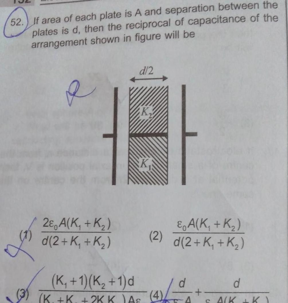
Capacitors52 If area of each plate is A and separation between the plates is d then the reciprocal of capacitance of the arrangement shown in figure will be e 2 A K K d 2 K K d 2 K K 2 K 1 K 1 d K K 2KK As 4 A K K d 2 K K 14 0 d A K K
Physics
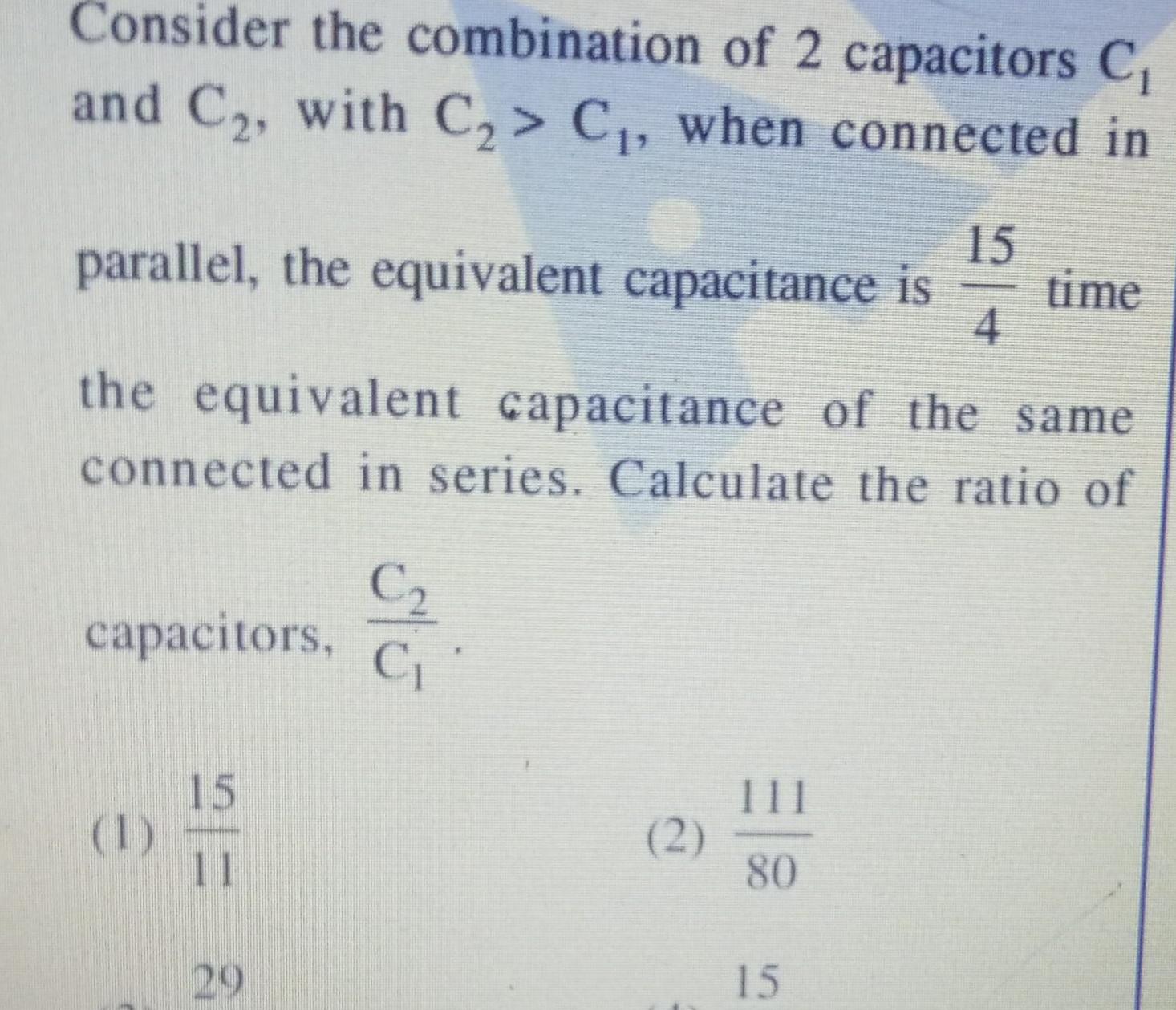
CapacitorsConsider the combination of 2 capacitors C and C with C C when connected in parallel the equivalent capacitance is time 15 4 the equivalent capacitance of the same connected in series Calculate the ratio of capacitors 1 15 11 29 C C 2 111 80 15

Physics
Capacitors1 How would you establish an instantaneous displacement current of 2A in the space between the two parallel plates of 1uF capacitor a 2 106 Vs c 4 106 Vs 1 b 3 106 Vs d 5x10 6 Vs sidiary

Physics
CapacitorsTwo capacitors of capacitance 2 F and 5 F are connected across a 7 V battery in series as shown in figure 2 F 7 V After the 2 capacitors are fully charged the battery is replaced by a closed switch The common potential Vc across the two capacitors is 10 Zero 5 F 7 V

Physics
Capacitorsshown in the figure The inner shell carries charge Q and outer one is neutral initially switch s is open Now switch is closed 2R R S The capacity of system is decreased The capacity of system is increased After closing the switch amount of heat released is Q 16 ER After closing the switch the amount of heat

Physics
CapacitorsFigure shows the graph of the current in a discharging circuit of a capacitor through a resistor of resistance 10 22 i A A i Find the initial potential difference across the capacitor ii Find the capacitance of the capacitor iii Find the total heat produced in the circuit iv Find the time constant of the circuit 10 2 5 2 t s

Physics
CapacitorsTwo condensers C 2 one of capacity C and the other of capacity are connected to a V volt battery as shown V L C 1 02 The work done by battery in charging fully both the condensers is 1 CV 2 2 CV 3 72

Physics
CapacitorsIn the given circuit calculate the potential difference across the 2 F capacitor in the steady state condition if internal resistance of battery is 1 ohm 10 252 www ww 1 L

Physics
CapacitorsFive identical plates each of area A are joined as shown in the figure The distance between successive plates is d The plates are connected to potential difference of V volt Find the charges of plates 1 and 4 11 2 3 4 5

Physics
Capacitors15 Consider the spherical shells of radius a and b a b D C b b 1 C C C C4 2 C C C C 3 C C3 C CA 4 C C C C3 C b C C Then which of the following holds good for the valu of their capacitances

Physics
CapacitorsMATCH LIST 1 Match List I against List Il referring to the adjacent figure Q List 1 P Effective capacitance between A and D Effective capacitance between F and E Effective capacitance between A and E R Effective S Effective capacitance between A and O 1 2 3 4 List II 45 C 13 15 C 8 45 19 9c 95 C A C 2C fo C 2C BT

Physics
CapacitorsIn the circuit shown a potential difference of 60V us applied across AB The potential difference between the points M and N is 1 10 V 2 15 V 60 V B G 20 3 20 V 4 30 V

Physics
Capacitorsne charge and energy ergy store the capacitor in Fig 2 b 54 when r 2 2 b For what value of r is the charge on the capacitor zero FIGURE 2 b 54 252 352 P R B D 61 Q 3 F S rQ 752

Physics
Capacitors9 Two capacitors 3 uF and 4 E are individually charged across a 6 V battery After being disconnected from the battery they are connected together with the negative plate of one attached to the positive plate of the other What is the final total energy stored AMU 2012 a 1 26 10 J Cop c 1 26 10 1 b 2 57 10 J d 2 57x10 1

Physics
CapacitorsRELATIVE VELOCITY 83 A ball A is dropped from a building of height 45 m Simultaneously another identical ball B is thrown up with a speed 50 ms The relative speed of ball Bw rt ball A at any instant of time is Take g 10ms b 10 ms d 50 m s a 0 c 25 m s 84 A ball A is thrown vertically upwards with speed u

Physics
CapacitorsA capacitor is connected across a battery which delivers a current 1 5 A at an instant in the capacitor Displacement current through the capacitor at that instant is 2A 1 A 1 5 A 1 75 A

Physics
Capacitors11 n identical condenser are joined in parallel and are charged to potential V Now they are separated and joined in series Then the total energy and potential difference of the combination will be 1 Energy and potential difference remain same 2 Energy remains same and potential difference is nV 3 Energy increases n times and potential differences is nV 4 Energy increases n times and potential difference remains same

Physics
CapacitorsFour capacitors are arranged to form the given circuit If this arrangement is connected across a voltage source then charge supplied by the source is 24 C Calculate the charge on capacitor A plution Given circuit can be redrawn as shown in figure As capacitance of both the branches are same so 24 C charge will be equally divided charge on capacitor A 12 C HH 3 L 2 F HH A 4 UTO C HH 6 F H B 8 DIN 6 F 2 F

Physics
Capacitors5 d d 2d Id d 3 4 5 2 6 There are six plates of equal area A and separation between the adjacent plates is d or 2d d A They are arranged as shown in figure Find the equivalent capacitance between points 2 and 5

Physics
Capacitors4 A circular coil of radius R and N turns has negligible resistance As shown in the schematic figure its two ends are connected to two wires and it is hanging by those wires with its plane being vertical The wires are connected to a capacitor with charge Q through a switch The coil is in a horizontal uniform magnetic field B parallel to the plane of the coil When the switch is closed the capacitor gets discharged through the coil in a very short time By the time the capacitor is discharged fully magnitude of the angular momentum gained by the coil will be assume that the discharge time is so short that the coil has hardly rotated during this time Ba

Physics
CapacitorsTwo parallel square plates each of side length a are arranged such that line joining centre of both the plates is perpendicular to planes of both plates Eight fixed charges are placed at comers of plate as shown in figure A charge particle of charge q and mass m is projected with initial velocity vo from centre C of one square plate towards centre C of other The length of line C C is 4a The speed of charge particle at mid point of line C C is 40 Find the value of x Neglect effect of gravity 18 la

Physics
CapacitorsIn the figure shown C 11 F and C 5 F then at steady state the potential difference across C is 5V the potential difference across C is 2V D the potential difference between points a and bis 4V the potential difference between the terminals of 15 V battery is 9V 7V 20 C Ly www 352 ISV 20

Physics
CapacitorsTwo capacitors each of capacitance C are each having a charge q initially connected as in fig the initial distance between the plates of each capacitor is do If the first plate of first capacitor and second plate of second capacitor will start move with constant velocity v then the electric current in the circuit at any time t from the start is neglect the resistance of connecting wires v 9 a

Physics
Capacitorsin the figure shown o is the surface I Dielectric Il Dielectric 0 on the upp PA Area of plate A d 3 24 3 meta A The ratio of energy density in 1st dielectric to second dielectric is B The ratio of energy density in 1st dielectric to second dielectric is in m mlin 3 30 C Total induced surface charge density on the interface of the two dielectric is 15 20 D Total induced surface charge density on the interface of the two dielectric is 15

Physics
CapacitorsTo get an output Y 1 in given circuit which of the following input will be correct 2012M B Co A a 1 b 1 c 1 TIMA BOOS C 0 1 0 54 Y

Physics
CapacitorsIn the given circuit the charge on the plates of 1 F capacitor when 100 V battery is connected to the terminals A and B will be A 1 F 2 F HH 3 F 3 50 C B

Physics
CapacitorsDerive an expression for the capacitance of a parallel plate capacitor when a dielectric slab of but of same area as that of the plates is inserted between the capacitor plates d separation between the plates dielectric constant K and thickness t d 2

Physics
CapacitorsCharged by a 10 v A 90 pF cap battery The capacitor is then disconnected from battery and connected to another charged 90 pF capacitor Final electrostatic energy stored by the system is NCERT Pg 82 F HE C 7 F

Physics
CapacitorsA capacitor is charged using an external battery with a resistance x in series The dashed line shows the variation of In I with respect to time If the resistance is changed to 2x the new graph will be A P C R B Q D S In I R P 2004

Physics
Capacitors26 Three parallel plates of the same metal and same area are placed between the plates of a parallel plate capacitor of capacity C If the thickness of each plate 1 is equal to th of the distance between the plates 5 of the original capacitor then the capacity of the new capacitor is 1 c 3 3 C 10 2 5 200 10 3

Physics
CapacitorsAn uncharged capacitor is connected to a battery On charging the capacitor 1 all the energy supplied is stored in the capacitor 2 half the energy supplied is stored in the capacitor 3 the energy stored depends upon the capacity of the capacitor only 4 the energy stored depends upon the time for which the capacitor is charged Z NODE02 BOAI BO TARGET PHY ENG MODULE 04 3 CAPACITOR 02 EXERCISE P

Physics
CapacitorsZ A cell E of emf 6V and internal resistance 20 is connected with another cell E of emf 4V and internal resistance 802 as shown in the figure The potential difference across points X and Y is P E 6V 20 1 10 0 V X E 4V 89 2 3 6 V

Physics
CapacitorsFigure shows a LCR circuit connected with a de battery of emf e and internal resistance R After a long time initially the capacitor was uncharged A Current through the inductor is E R 8R C B Charge stored in the capacitor is 4 C Charge stored in the capacitor is C 2 R moooo 2R 2R L D Potential difference across the terminals of battery is

Physics
CapacitorsA parallel plate capacitor of C is charged with a battery of emf V volts A dielectric slab of dielectric constant K is placed between the plates to fully occupy the space The battery remains connected The new electrostatic force of attraction between the plates F is related with initial force F as 1 K F 2 KF 3 F 4 FLY

Physics
CapacitorsA circuit consists of two capacitors a 24V battery and an AC source connected as shown in figure The AC voltage is given by 20 cos 120xt V where t is in second A Charge on capacitor C as function of time Q 30 C cos 120mt 36 C B Steady state current is 33 9mA sin 120nt n C Maximum energy stored in capacitor C C is 36 mJ D Minimum energy stored in capacitors C and C is 36 J 20V6 24V C 13 F C L1 5 F

Physics
Capacitors7 203 A charged oil drop of mass 2 5x 10 kg is in space between the two plates each of area 2x10² m of a parallel plate capacitor When the upper plate has a charge of 5 x 10 7 C and the lower plate has an equal negative charge then the oil remains stationary The charge of the oil drop is take g 10 m s b 9 10 6 C d 1 8x 10 4 C a 9 10 C c 8 85x 10 13 C

Physics
CapacitorsIf nothing is mentioned then assume the battery to be disconnected and A parallel plate capacitor is connected to a battery V const and a slab of dielectric constant is insert between the plates then the total energy delivered by the battery is divided into two parts Half is used to insert the slab work is done by field explain Half is stored in the form of electrostatic potential energy i ii

Physics
CapacitorsAn arrangement of smooth pair of long conducting rails which are resistanceless are joined to a charged capacitor The rails are connected by a rod of mass and length and resistance R Vertical magnetic fie uniform The rod is initially at rest It starts moving due to the influence of magnetic field What should be the mass of the rod in mg so that its kinetic energy in steady state is maximum Take 1 1m B 2T C 1 F R 10 mass m

Physics
Capacitors13 Find the equivalent capacitance between points A and B for the network shown in Fig 2 89 C Ao 1 F C3 C HH 1 F 1 F C 2 F Ans OB 8 3 HF Fig 2 93 18 Find

Physics
CapacitorsAakash Institute 70 In the circuit shown below to have same potentials of points a and b a dielectric of constant K 2 should be completely filled in C 1 F HH C 4 F 1 1 B 1 C1 and C3 3 C2 and C4 b C 4 F C 4 F 74 Ac dir 2 C1 and C4 4 C2 and C3 capacitance 400 F is charged upto a ther capacitor of C 7

Physics
CapacitorsFour capacitors and a battery are connected as shown The potential drop across the 7 uF capacitor is 6V Then the 12 F 7 F 3 F A Potential difference across the 3 uF capacitor is 10V B Charge on the 3 uF capacitor is 42 C C Emf on the battery is 30V D Potential difference across the 12 F capacitor is 10V 3 9 F

Physics
Capacitors204 A capacitor of 4 uF is connected as shown in the circuit The internal resistance of the battery is 0 52 The amount of charge on the capacitor plates will be NCERT Exemplar a 0 b 4 C Q4 F HH c 16 C 2 5 V www 222 1002 d 8 C of two dielo 209 A

Physics
Capacitors2 A parallel plate vacuum capacitor with plate area A and separation x has charges Qand Q on its plates The capacitor is disconnected from the source of charge so the charge on each plate remains fixed i What is the total energy stored in the capacitor ii The plates are pulled apart an additional distance x 4 What is the change in the stored energy

Physics
CapacitorsA parallel piate capacitor without any dielectric within its plates has a capacitance C and is connected to a battery of emf V The battery is disconnected and the plates of the capacitor are pulled apart until the separation between the plates is doubled What is the work done by the agent pulling the plates apart in this process J K CET 2012 a c NI CV 3 CV b 3 2 CV d CV

Physics
CapacitorsA parallel plate capacitor without any dielectric within its plates has a capacitance C and is connected to a battery of emf V The battery is disconnected and the plates of the capacitor are pulled apart until the separation between the plates is doubled What is the work done by the agent pulling the plates apart in this process J K CET 2012 a CV 2 3 c CV 2 3 b CV 2 d CV

Physics
CapacitorsIn the circuit shown initially the switch is open and all the capacitors are uncharged Consider the first 100 s interval after the switch is closed Find the total energy stored in the capacitors and the total energy dissipated in the resistance in this 100 s interval Internal resistance of the battery does not exceed a few ohms HH C 3 F HH C 6 F Vo 200 V HE C 6 F R 100 k HH C 3 F Ans 9x10 2 J 1x10 2 J

Physics
CapacitorsTo increase the charge on the plate of a capacitor implies to 1 decrease the potential difference between the plates 2 decrease the capacitance of the capacitor 3 increase the capacitance of the capacitor 4 increase the potential difference between the plates

Physics
CapacitorsIn an LC oscillator circuit L 10 mH C 40 l If initially at t 0 the capacitor is fully charged wit 4uC then find the current in the circuit when th capacitor and inductor share equal energies 1 0 2 mA 2 4 4 mA 3 03 mA 4 2 mA

Physics
CapacitorsA conductor of length 1m radius r 1 cm resistivity p 2 5 10 8 Q2 m independent of temperature is connected to a cell of constant emf 5 V as shown in the figure Initially the conductor is at room temperature To 300 K At t 0 the switch Sw is closed The conductor starts radiating heat to the environment according to Newton s law of cooling and the constant of cooling is K 10 sec Heat capacity of the conductor is J K Answer the following questions Resistance of connecting wire is negligible 1 What is the steady state temperature of the conductor A 300 K C 9700 K 2 B 10 000 K D 10 300 K Sw Find the rate of heat radiation through the conductor when it has become constant A x 105 J sec B 105 J sec C 10m x 104 300 J sec B can t be calculated