Current Electricity Questions and Answers

Physics
Current Electricity05 A plane loop shown in Fig 3 91 is shaped as two squares with sides a 20 cm and b 10 cm and is introduced into a uniform magnetic field at right angles to the loop s plane The magnetic induction varies with time as B Bo sin oot where Bo 10 mT and 100 s Find the amplitude of the 0 1 a JEE MAIN Fig 3 91 b current induced in the loop if its resistance per unit length is equal to p 50 m2 m The inductance of the loop is to be neglected

Physics
Current Electricityrom of are chen 28 A galvanometer has resistance G and full scale deflection current i To convert this galvanometer into an ammeter of range 10 i a shunt S G 9 connected in parallel with G Now we want to measure potential difference with the help of this ammeter What is the maximum value of potential difference which can be measured with the help of this a 10 i G c 9 i G b i G 10 d is FIG G

Physics
Current Electricity3 Five identical cells are connected in parallel Now polarity of one of the cells is reversed Percentage change in equivalent emf will be a 10 c 40 b 20 d 60

Physics
Current Electricityt ww E AAT H a E b r 08 ou 3081 0 m E No current a c In which of the above cells the potential difference between the terminals of a cell exceeds its emf B 6 C c D d intonce R is connected to a cell of internal resistance 5 22 The value of R is varied from E b

Physics
Current Electricity24 The n rows each containing m cells in series are joined in parallel Maximum current is taken from this combination across an external resistance of 30 resistance If the total number of cells used are 24 and internal resistance of each cell is 0 502 then a m 8 n 3 c m 12 n 2 b m 6 n 4 d m 2 n 12
Physics
Current Electricity40 A series parallel combination of batteries consisting of 300 identical cells each with an internal resistance r 0 3 2 is loaded with an external resistance R 10 22 The number n of parallel groups consisting of an equal number of cells connected in series at which the external resistance generates the highest thermal power is a 2 c 4 b 3 d 6

Physics
Current Electricity9 In the figure the potentiometer wire of length 1 100 cm and resistance 9 22 is joined to a cell of emf E 10 V and internal resistance 12 Another cell of emf E2 5 V and internal resistance r2 20 is connected as shown The galvanometer G will show no deflection when the length AC is a 50 cm A E 10 V 12 G E 5 V 12 22 b 55 E C 20 Up B b a

Physics
Current Electricity5 Resistance of a wire at temperature t Cis R Ro 1 at bt Here Ro is the temperature at 0 C The temperatu coefficient of resistance at temperature t is a 2bt b a 2bt a c 1 at bt 1 at bt a 2bt d constant

Physics
Current Electricity21 In the circuit shown in figure when switch S 15 closed and S is open the ideal voltmeter shows a reading of 18 V When switch S2 is closed and S is open the reading of the voltmeter is 24 V When S and S both are closed the voltmeter reading will be a 14 4 V E IT www b 20 6 V S 692 www S 12Q c 24 2 V V d 10 8 V

Physics
Current ElectricityVM 48 A battery of emf E and internal resistance r is connected across a 10 resistance R Resistance R can be adjusted to any value greater than or equal to zero A graph is plotted between the current passing through the resistance I and potential difference across the terminals of the battery V Maximum power developed across the resistance Ris a 5 W b 10 W 0 15 c 15 W 2 1 A d 25 W

Physics
Current Electricity20 For what value of R in the circuit as shown current passing through 4 2 resistance will be zero a 19 www 292 10V b 29 452 6V HH 4V www c 32 R d 4 Q

Physics
Current ElectricityMr Vivek Taparia performed an experiment to verify Ohm s law He connected following circuit to measure voltage and current k R wwww Here R is the unknown resistance V the voltmeter A the ammeter and K is the key The value of R from following readings is given by a 10 ko then find the value of a B V volt 12 3 4 5 I mA 1 40 2 83 5 68 7 11 8 54 Question Type Integer Type

Physics
Current Electricity18 A resistance of 302 is connected in the left gap of a meter bridge and a resistance 62 in the right half Total resistance of the 1 m long meter bridge wire is 90 The jockey is pressed at a point on wire in such a way that this point divides meter bridge wire in the ratio 2 1 A cell of emf 15 volt and internal resistance 12 is connected across the meterbridge wire Find the reading of ideal galvanometer connected in series to the jockey Neglect the resistance of all other elements a Zero b 0 5 A c d 1 A 1 5 A

Physics
Current ElectricityDuring an experiment with a metre bridge the galvanometer shows a null point when the jockey is pressed at 40 0 cm using a standard resistance of 90 as shown in the figure The least count of the scale used in the metre bridge is 1 mm The unknown resistance is R 40 0cm 9022 www

Physics
Current Electricity39 In the situation shown the readings of ideal ammeters A and A are in the ratio 50 VI 1 1 1 2 1 3 3 3 1 R RR RR RR R A A

Physics
Current ElectricityQ8 Two capacitors of capacity 10uF each are connected in parallel The parallel combination is further connected in series with two capacitors of capacity 20 F 40 F respectively Calculate the equivalent capacity of the circuit

Physics
Current ElectricityB The resistance between the terminal point P and Q of the given infinitely long circuit will be in 92 12 12 12 ww ww P www A 19 1 1 3 2 1 3 3 3 1 4 3 3 12 19 ww 12 12 upto infinity 19

Physics
Current Electricity5 A parallel plate capacitor has a plate area A and separation d A battery charges the plates to a potential difference V The battery is now disconnected and a dielectric slab of dielectric d constant k thickness 2 and area A is introduced The ratio of energy stored in the capacitor before and after the slab is introduced will be 1 3 1 k 1 k 2k 2 k 4 27 CACOA d 2k 1 k

Physics
Current ElectricityIn a meter bridge an unknown resistance P is connected in the left gap and a 500 resistance in the right gap Null point is obtained at x cm from the left end The unknown resistance now shunted with an equal resistance Find the value of the resistance in the right gap so that the null point is not shifted

Physics
Current Electricity792 Part AC is 20 cm long Two resistors and two ideal cells are connected as shown 1v A 4 1v 292 O Of the points A R and C the potential is maximum at p A O B O 1 502 www C C B Clear Response

Physics
Current ElectricityThe internal resistances of two cells shown a 0 1 and 0 30 If R 0 22 the potential difference across the cell 2V 0 102 2V 0 302 A B will be zero B A will be zero C A and B be 2V 0 20 B D A well be 2V and B will be 2V

Physics
Current ElectricityC 2mA from right to left The current in a wire varies with time according to the equation I 4 2t where J is in ampere and t is in sec Calculate the quantity of electricity which has passed through a cross section of the wire during the time t 2 sec to t 6 sec A 7C B 14 C C 24 C D 48 C frame cross sectional area and they carry same current If their lengths are

Physics
Current Electricity3 0 6A 4 0 8A An inductor of 12 mH and a resistor of 4K are connected in series across a battery of 240 V through a switch After closing the switch the current in the circuit starts growing When the current is 15 mA the potential difference across the inductor will be 2 120 V 1 60 V 3 180 V 4 240 V An emf induced in a secondary coil is 10000 V when the current brake in th

Physics
Current ElectricityFor a cell the graph between the potential difference V across the terminals of the cell and the current 1 drawn from the cell is shown in figure The emf and the internal resistance of the cell are V volt 2 1 5 1 0 5 A 2V 0 40 B 2V 0 502 c2V 0 40 D 2V 0 40 1 2 3 4 5 I amp

Physics
Current Electricityto ac age of ta de F d R 25 92 L 1 5 H C 45 F 6 An inductor of reactance 1 22 and a resistor of 2 92 are connected in series to the terminals of a 6 V rms ac source The power dissipated in the circuit is a 8 W c 14 4 W b 12 W d 18 W

Physics
Current ElectricityIn a gas discharge tube if 1 25 10 6 electron are flowing per sec from left to right and 1 25 10 6 protons are flowing per sec from right to left in a given cross section then calculate the strength of the current and also find its direction A 4mA from left to right C 2mA from right to left B 4mA from right to left D 2mA from left to right ding to the equation I 4 2t where I is in ampere and t is in sec

Physics
Current ElectricityTwo batteries in opposition are joined as shown The internal resistance of 6 V battery is 2 22 and 4 V battery is 82 The potential difference between the points X and Y is 4 V a 2V 202 www 802 www b zero 217

Physics
Current Electricity32 A 1 5 F capacitor is charged of 60 V The charging battery is then disconnected and a 15 mH is connected in series with the capacitor so tha LC oscillations occur Assuming that the circus contains no resistance the maximum current in this coil shall be close to a 1 4 A c 0 8 A b 1 2 A d 0 6 A 3 A condenser of capacity i

Physics
Current Electricity12 An alternating voltage of angular frequency is circuit an induced in electric consisting of inductance L and capacitance C connected in parallel Then across the inductance coil 1 a current is maximum when w 2 b current is minimum when w 2 d voltage is maximum when w c voltage is minimum when w 19 19 19 19

Physics
Current Electricity70 The self inductance of a choke coil is 10 mH When it is connected with a 10 V dc source then the loss of power is 20 watt When it is connected with 10 volt ac source loss of power is 10 watt The frequency of ac source will be a 50 Hz b 60 Hz c 80 Hz d 100 Hz

Physics
Current ElectricityConsider the circuit shown below I is constant current source meaning that no matter what device is connected between points A and B the current provided by the constant current source is always 1 the same 4R 2R 2R 2R THE NA GROUP A If an ideal voltmeter is connected between A and B the reading of voltmeter is 1 R B If an ideal voltmeter is connected between A and B the reading of volume is 21 R C If an ideal ammeter is connected between A and B the reading of ammeter is 4R D If an ideal ammeter is connected between A and B the reading of ammeter is Is 96

Physics
Current Electricity15 15 What is the equivalent resistance of the three resistors on the left to the 6 V cell in the above fic 1 10 2 2 99 3 592 247422 16 What is the current drawn from the cell in the circuit 1 6 A 3 3 3 4 A 264 17 What is the current through the 20 2 resistor on the left of the 6 V cell in the figure 2 A A 23 2002 www 10 92 ww V wwwwww 2092 wwww A 2 2 A 2 2 4 A 15 3 15 18 What is the voltage drop across the three resistors on the left of the 6 V cell in the figure 2 6 V 4 A 2 A 15 3 4 V 19 What is the current through the 10 2 resistor on the right of the 6 V cell in the figure 1 8 4 V 3 3 A

Physics
Current Electricity3 An LCR series ac circuit is at resonance with 10 V each across L C and R If the resistance is halved the respective voltages across L C and Rare a 10 V 10 V and 5 V c 20 V 20 V and 5 V b 10 V 10 V and 10 V d 20 V 20 V and 10 V 56 The Q C 32 a 15 57 Figure variabl

Physics
Current ElectricityTwelve wires each of resistance 10 0 are joined to form a cube and an ideal battery of emf 30 V is also connected In series with one of resistance of cube as shown in figure The current through the battery is 30 V A B 2017 C 15 36 A

Physics
Current ElectricityThe diffusion current in p n junction is From n side to p side From p side to n side hr min From n type to p side if junction is forward O biased and in opposite direction if it is reversed biased From p side to n side if junction is forward O biased and in opposite direction if it is

Physics
Current Electricity1 An ammeter and a milliammeter are converted from identical galvanometers Which one has smaller resistance 1 Ammeter 2 Milliammeter 3 Both have equal resistances 4 The resistance of ammeter may be more than or equal to that of milliammeter depending

Physics
Current Electricity16 Two identical capacitors have the same capacitance C One of them is charged to potential V and other to V The negative end is joined with the positive end of other capacitor When the other two remaining ends are connected the change in energy of combined system is 1 C V V 2 1 C V V 3 C V V 4 4 C V V 4

Physics
Current ElectricityIn a meter bridge the null point is found at a distance of 25 cm from A If now a resistance of 10 2 is connected in parallel with S th null point occurs at mid point of AB The value of R is A B 6 67 92 1 67 Q 2 67 92 4 67 9 Marks 4 00 1 B
Physics
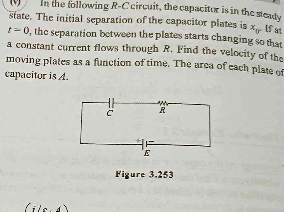
Current ElectricityIn the following R C circuit the capacitor is in the steady state The initial separation of the capacitor plates is t 0 the separation between the plates starts changing so that a constant current flows through R Find the velocity of the moving plates as a function of time The area of each plate of capacitor is A il 4 HH C F E R Figure 3 253

Physics
Current ElectricityAssuming that the two diodes D and D used in the electric circuit shown in the figure are ideal find out the value of the current flowing through 122 resistor D 252 wwwww D 292 K www He 152

Physics
Current Electricity6 For the arrangement of the potentiometer shown in the figure the balance point is obtained at a distance 75 cm from A when the key k is open A E 2V E 1 5V Hi ww T ww 602 B The second balance point is obtained at 60 cm from A when the key k is closed Find the internal resistance of the battery E 1 1 5 Q 2 202 3 0 5 2 4 10

Physics
Current Electricitynected across the terminals of a cell the Q When a resistance is current is I When the resistance is changed to R the current is I2 The internal resistance of the cell is Odisha JEE A B C D I R I R 1 12 I R I2 R I1 I2 I R 12 R 11 12 Solution 12 12 R2 12 R 11 12 Odisha JEE 2010 Current Electricity Let the emf of cell be E and intemal resistance be r Then I On dividing we get or r E r R r R r R 12 R2 11 R 11 1 and I E r R Report Erro

Physics
Current ElectricityYou have 20 identical cells When these are connected in series with resistance R current through circuit is I Now your naughty friend reverse some of the cell then current through circuit reduce to Calculate the no of cells reversed A B 8 4 Marks 4 00 1 00 16

Physics
Current Electricityn e 29 A potentiometer is an ideal device off measuring potential difference because 1 It uses a sensitive galvanometer 2 It does not take current from the potential difference to be measures 3 It is an elaborate arrangement 4 It has a long wire hence heat developed is quickly radiated

Physics
Current ElectricityThe diffusion current in p n junction is O From n side to p side From p side to n side From n type to p side if junction is forward bias and in opposite direction if it is reversed biased From p side to n side if junction is forward biase and in opposite direction if it is reversed biased

Physics
Current Electricity27 The figure shows a circuit diagram of a Wheatstone Bridge to measure the resistance G of the galvanometer The relation will be satisfied only when ww PR QG 1 The galvanometer shows a deflection when switch S is closed 2 The galvanometer shows a deflection when switch S is open 3 The galvanometer shows no change in

Physics
Current Electricity15 To measure a potential difference across a resistor of resistance R a voltmeter of resistance R is used To measure the potential with a minimum accuracy of 95 then A R 5R 3 B R 19R C R 10R D R 19R

Physics
Current ElectricityD The charge on condenser will reduce to one third 4 A capacitor of capacity C is connected with a battery of potential V in parallel The distance between its plates is reduced to half at once assuming that the charge remains the same Then to charge the capacitance upto the potential V again the energy given by the battery will be A CV4 B CV 4 C 3CV 4 D CV 150

Physics
Current ElectricityTYPE questions Each question has 4 choices 1 Read More For the configuration of two charges shown the electric field will be zero from charge Q at distance equals to Q K D 2 85 d 4Q

Physics
Current ElectricityTwo identical slabs of a given metal are joined together in two different ways as shown in figures a and b What is the ratio of the resistances of these two combinations Delhi 2010 C a b