Current Electricity Questions and Answers

Physics
Current ElectricityCE The equivalent resistance between the terminal points A and B in the network shown in figure A 7R B 5R R R R R ww R ww R ww R R 7R R R B 5R pryExpos 37 38

Physics
Current ElectricityA 3 V DC supply with an internal resistance of supplies a passive non linear resistance characterized by the relation VNL 1 2 NL The power dissipated in the non linear resistance is 1 1 0 W 2 1 5 W 3 2 5 W 4 3 0 W

Physics
Current ElectricityA 10 volt battery with internal resistance 202 is connected in a circuit shown in the diagram Choose CORRECT statement s 152 10volt 1 22 U If power dissipated in resistance R is maximum then R 20 If power dissipated in outside circuit circuit other than battery is maximum then R If power dissipated in resistance R is maximum then R 30 6 5 If power dissipated in outside circuit circuit other than battery is maximum then R 60 22

Physics
Current ElectricityTwo magnetically uncoupled inductive coils have Q factors 9 and 92 at the chosen operating frequency Their respective resistances are R and R When connected in series their effective Q factor at the same operating frequency is 1 91 92 2 1 91 1 92 3 91R 92R2 R R 4 R g R R R

Physics
Current ElectricityA galvanometer resistance R together with an unknown resistance r in series is connected across two identical batteries each of 1 5V When the batteries are connected in series the galvanometer red current of 1A and when the batteries are in parallel then current it records is 0 6A Choose the correct statement s 0 The internal resistance of the battery is 1 3 ohm HR 0 ohm then r 7 3 ohm 9 If one cell is removed then current in the circuit is 16 A 7 If one cell is removed then current in the circuit is 16

Physics
Current ElectricityIf a resistance R is connected in parallel with resistance R in circuit then possible value of current through R and value of R is 1 24 2R R www R wwww Hill A 2 1 2R OP

Physics
Current Electricity15 Two identical cells each of emf E and each of internal resistance r are connected in series with an external resistance R then power P became maximum across R Choose correct graph 1 E2 4R 3 E R r R 2r R 2 AR 4 E 4R AR 2R R P A r 2R P n R 2r R R

Physics
Current Electricity2 If two bulbs 60 W 250 V and 120 W 250 connected in parallel across a 400 V Then of the following option is correct 1 60 W bulb will be fused 2 120 W bulb will be fused 3 No bulb will be fused 4 Both bulbs will be fused

Physics
Current ElectricityIn the circuit diagram The current through 10 ohm is 1 25 A The current through 5 ohm is 2 5 A The current through 50 is 1 25 A The current through 100 is 2 5 A 25V 5 20 301 US 10V T12

Physics
Current ElectricityA circuit consists of eight batteries each having an emf of 1 5 V and an internal resistance of 0 25 92 connected in series as shown What would be the reading in a voltmeter connected across any one of the batteries A zero B 1 5 V V 16 16 F

Physics
Current Electricity50 23 Figure shows a potentiometer circuit for comparison of two resistances The balance point with a standard resistor R 10 0 2 is found to be 58 3 cm while that with the unknown resistance X is 68 5 cm Determine the value of X What might you do if you failec to find a balance point with the given cell o emf H Yineol A R www M 2014 B

Physics
Current ElectricityThe potential difference applied to an X ray tube is 5kV and the current through it is 3 2 mA Then the number of electrons striking the target per second is O 2 10 6 O 5 10 O 1 10 7

Physics
Current Electricity5 20 25 30 4 35 39 40 44 45 49 50 3 54 55 58 59 60 Multiple Choice Select 1 out of 4 options for the question below 63 64 65 The resultant resistance between point A and B is 102 www 68 69 70 A Options 10 10 10 50 50 wwww 10 Q2 ww a 2 10 0 Clear Response B

Physics
Current ElectricityA straight hollow cylindrical conductor of length inner radius r and outer radius a has resistivity where r is distance from it s axis If both ends of conductor are maintained at a potential difference a current density at distance r from axis

Physics
Current Electricity10 The Wheatstone s network is shown in the figure If the key K is closed then the galvanometer will lsd Jon Iliw www P 20 92 ww R 20 S2 www Q 10Q2 ww ww S 2092 D K a deflect on the left side b deflect on the right side c deflect on either side d not show any deflection 2018

Physics
Current Electricity0 A wire of resistance 4 Q2 is used to wind a coil of radius 7 cm The wire has a diameter of 1 4 mm and the specific resistance of its material is 2 x 10 72 m The number of turns in the coil is a 50 b 40 c 60 d 70

Physics
Current Electricity2 21 1 5 2 1 5 3 1 5 4 5 For hydrogen gas cp c a and for a oxygen gas Cp C b then the relation between a and bis where c c are gram specific heats 1 a 16 b 3 a b 2 b 16 a 4 None of these

Physics
Current ElectricityQ A copper wire of uniform cross sectional area 3 x 10 6 m carries current 15 A Find the draft speed of electrons in the wire Assume that each copper atom contributor are free electron to the wire pcu 9x10 kg m

Physics
Current Electricity1 The current density varies with radial distance 1 as J ar in a cylindrical wire of radius R The current passing through the wire between radia distance R 3 and R 2 is 65 a R4 a c 2592 65 a R 2938 3 b d 25 a R4 72 2 81 R 144

Physics
Current ElectricityQ10 A 50 resistor is connected to a battery The battery s emf is 50V and it has an internal resistance of 50 What is the voltage across the 50 resistor O A 5V O B 25V O C 10V O D 50V Resources BAD

Physics
Current ElectricityQuestion 3 7 marks A coaxial cable is made up of two conductors one which has an inner radius of 1 5 cm and one which has an outer radius 5 cm The length of the cable is 200 m A potential difference of 3 kV is maintained between the conductors a Use the analogy between the D and J fields to calculate the current through the medium medium which is characterised by 1 8 and 10 S m b Calculate the power dissipated in the medium

Physics
Current ElectricityFor different values of resistance R powe consumptions in R are given Then which of the following values are not possible F 4 V ww R a 2 W b 5 W c 8 W 1 Only c www 19 3 abc d 4 W 2 b c 4 All

Physics
Current ElectricityIn the circuit shown below if the source voltage Vs 100253 13 V then the Thevenin s equivalent voltage in Volts as seen by the load resistance R is Vs 30 140 www V j692 000 401 10 V VL1 50 www R 10 2

Physics
Current ElectricityWhen a resistance of 2 ohm is connected across the terminals of a cell the current is 0 5A When the resistance is increased to 5 ohm the current is 0 25A The emf of the cell is 1 1 0V 2 1 5V 3 2 0V

Physics
Current Electricity15 An energy source will supply a constant current into the load if its internal resistance is A equal to the resistance of the load C zero W CE0055 AIEEE 2005 B very large as compared to the load resistance D non zero but less than the resistance of the loa CE005

Physics
Current Electricitym The figure shows a network in which the cells is ideal and it has an emf E The potential difference across the resistance 2R is E 4R

Physics
Current Electricitya A C meters can measure D C also X b If A C meter measures D C there scale must be linear and uniform c A C and D C meters are based on heating effect of current d A C meter reads rms value of current g 2 b c 3 c d 4 d a a b

Physics
Current Electricitynetwork of resistances is 202 D neet prep 1 2 3 20 3V ww 252 20 252 www 202 202 M E 202 www 202 6 Five equal resistances each of resistance R are connected as shown in the figure A battery of V volts is connected between A and B The current flowing in AFCEB will be Current Electricity Super Revision Live Session 27 March 2021 Contact Number 9667591930 8527521718 0 15 V HFF AFMF FM TIF 5000 electroplaques per row 0 25 www 500 2 100 rows 4 m Pag The water surrounding the eel completes a circuit between the head and its tail If the water surrounding it has a resistance of 500 2 the current an eel can produce

Physics
Current Electricity3 R RB R 4 Information is not sufficient 16 Variation of current passing through a conductor as the voltage applied across its ends as varied is shown in the adjoining diagram If the resistance R is determined at points A B C and D we will find that r 1 Rc RD 2 RB RA 3 Re RB 4 None of these 17 For a cell the graph between the potential difference V across the terminals of the cell and the current 1 drawn from the cell is shown in the figure The e m f and the internal resistance of the cell is V Volts 2 0 1 5 1 0 0 5 0 D 1 2 3 4 5 Hamperes 1 2V 0 522 2 2 V 0 402 3 21 0 522 4 2 V 0 492 18 In the circuit in the figure if the potential at point A is taken to be zero the potential at point B is 1AI R www A 1 IV 3 2V R 2 V D www Hill 00 Hilt 1 2 1 2 4 9 3 9 4 4 1 2 www VIAC2A E 19 Six similar bulbs are connected as shown in the figure with a DC source of emf E and zero internal resistance The ratio of power consumption by the bulbs when i all are glowing and ii in the situation when two from section A and one from section B are glowing will be 292 B 00 192 ww E g 8 B 2 A 4 5 W 1 5 V 2 2V 4 1V 20 A torch bulb rated 4 5 W 1 5 V is connected as shown in Fig 7 35 The emf of the cell needed to make the bulb glow at full intensity is

Physics
Current Electricity20 A torch bulb rated 4 5 W 1 5 V is connected as shown in Fig 7 35 The emf of the cell needed to make the bulb glow at full intensity is 4 5 W 1 5 V 192 ww E r 2 672 Pa

Physics
Current Electricity62 A thin flexible wire of length L is connected to two adjacent fixed points and carries a current I in the clockwise direction as shown in the figure When the system is put in a uniform magnetic field of strength B going into the plane of the paper the wire takes the shape of a circle The tension in the wire is A IBL XXXXXXXX XXXXXXXX XXXXXXXX XXXXXXX XXXXXXXX XXXXXX B IBL C IBL D IBL ATT

Physics
Current Electricity61 When a wire of uniform cross section a length and resistance R is bent into a complete circle resistance between two of diametrically opposite points will 2005 be a R 4 b 2R c 4R d R 2

Physics
Current Electricityn vn he Six similar bulbs are connected as shown in the figure with a DC source of emf E and zero internal resistance The ratio of power consumption by the bulbs when i all are glowing and ii in the situation when two from section A and one from section B are glowing will be A 00 00 joo 1 2 1 2 4 9 3 9 4 4 1 2 E B 00 00

Physics
Current ElectricityIn the circuit shown in figure find the value of r interna resistance of the cell for which power transferred by the cell is maximum 50V 1 40 2 120 3 162 4 80 1202 www 452 ww 402 ww 1202 www

Physics
Current ElectricityA cone of the radius of base 1 m and height 2 m is placed with its base in the xz plane in a region with the uniform electric field E 20 i V m as shown in the figure The magnitude of electric flux linked with the cone is KZ 1 Zero 2 10 Vm 3 20 Vm X 1 2 3 4 26 Th its enc 1 2 3 4 27 A

Physics
Current ElectricityA three phase 100 MVA 25kV generator has solidly grounded neutral The positive negative and the zero sequence reactances of the generator are 0 2 pu 0 2 pu and 0 05 pu respectively at the machine base quantities If a bolted single phase to ground fault occurs at the terminal of the unloaded generator the fault current in amperes immediately after the fault is

Physics
Current Electricitye y 0 n d 9 In the Wheatstone s bridge shown in figure X Y and A B The direction of the current between ab will be 1 From a to b From b to a con www 1 2 3 From b to a through c b y

Physics
Current ElectricityThe instantaneous value of current in an A C circuit is I 2 sin 100 t 3 A The current will be maximum for the first time at Question Type Single Correct Type 1 2 3 4 t t 1 100 t S 1 200 1 t 400 S 60 S 1 S

Physics
Current Electricity2 0 kn and a 4 0 k resistor are connected in rallel this combination is connected in series h a 1 1 k resistor Part A If each resistor is rated at 0 7 W maximum without overheating what is the maximum voltage tha be applied across the whole network Express your answer using two significant figures Vmax VA 51 8 B V

Physics
Current ElectricityFor the circuit shown in the figure Figure 1 find the current through and he potential difference across each resistor You may want to review Page gure 12 V 3 0 2 ww 162 ww ww 4 02 48 02 1 of 1 Part G Find the current through 16 12 resistor Submit Request Answer Part H VAZO Find the potential difference across 16 52 resistor V VAX 4 V

Physics
Current ElectricityIn an LCR series ac circuit the voltage across L C and R is 10V each If the inductor is short circuited the voltage across the capacitor would become 1 10V 3 20 2V 2 20 10

Physics
Current ElectricityCombination Contact Number In the network of resistors shown in the adjoining figure the equivalent resistance between A and B is A 302 302 of Resistors 9667591930 8527521718 1 54 ohm 2 18 ohm 3 36 ohm 302 302 302 302 302 302 352 352 302 352 B

Physics
Current ElectricityBy using only two resistance coils singly in series or in parallel one should be able to obtain resistances of 3 4 12 and 16 ohms The separate resistances of the coil are 1 3 and 4 2 4 and 12 3 4 16 and 3 12 and 16
Physics
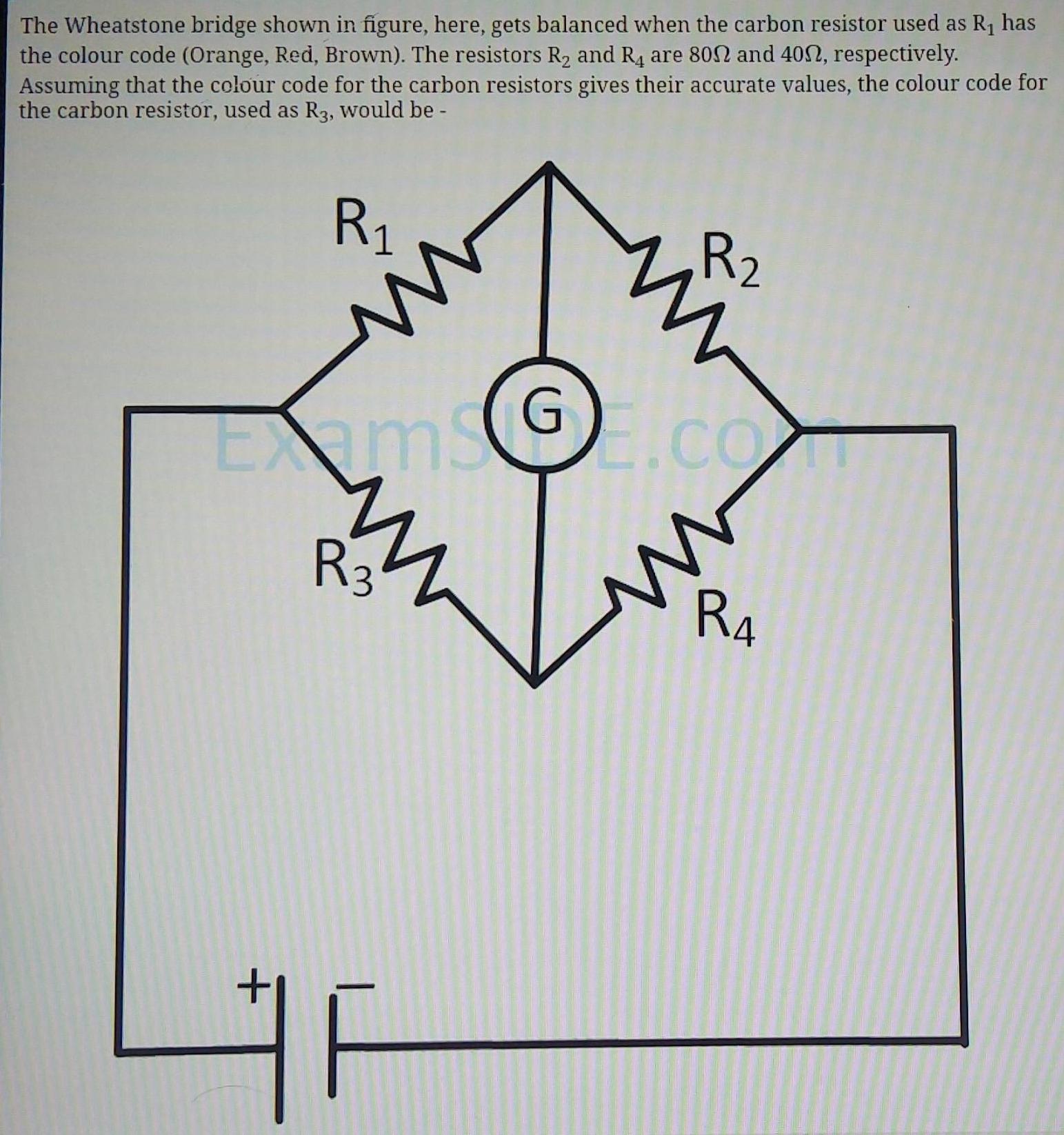
Current ElectricityThe Wheatstone bridge shown in figure here gets balanced when the carbon resistor used as R has the colour code Orange Red Brown The resistors R and R4 are 800 and 4002 respectively Assuming that the colour code for the carbon resistors gives their accurate values the colour code for the carbon resistor used as R3 would be R 1 ww EmsGE co ww R3 R 2 F www R4
Physics
Current Electricity19 A voltmeter has resistance of 2000 ohms and it can measure upto 2V If we want to increase its range to 10 V then the required resistance in series will be 1 2000 2 2 4000 2 3 6000 2 4 8000 2

Physics
Current ElectricityIn circuit shown below the resistances are given in ohms and the battery is assumed ideal with emf equal to 3 volt The voltage across the resistance R4 is HHH 3 V 1 0 4 V 2 0 6 V 3 1 2 V 4 1 5 V 5052 www R 5012 R R R 602 R 302 R 3052 18

Physics
Current Electricityoblem 3 18 What will be the resistance of a sem circle shown in fig between its two end faces Giver that radial thickness is 3cm axial thickness is 4cm inner radius is 6cm and specific resistance E 4x10 ohm cm C Solution R P R A R 4x10 6 9 2 12 4 10 x 7 5 Pm 1 2 A

Physics
Current ElectricityExample 3 12 cells each having the same emf values are connected in series and are kept in a closed box Some of the olls are wrongly connected This battery is connected in series with an ammeter and two cells identical with the others The current is 3 A when the cells and the battery aid each other and it is 2 A when the cells and the battery oppose each other How many cells are wrongly connected

Physics
Current Electricityneet prep 402 1 1 V 2 1 5 V 3 V 352 ww 652 Mini Test 9 Combination of Resistors Contact Number 9667591930 8527521 1 PI P2 2 Pites 2 3 P P2 4 2 p P 12 In the circuit shown in the adjoining figure the cur between B and D is zero the unknown resistance is of B

Physics
Current Electricity16 A galvanometer has constant 10 A deflection a current of 1 A pass through the coil The area of coil is 0 02 m 2 ad magnetic field of O 02 T is act on coil Answer the following any 4 1 Convert it into an ammeter